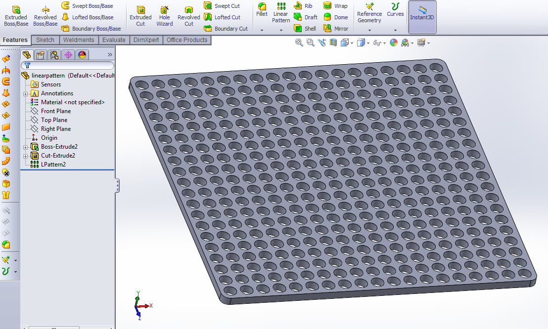
In the last installment of my epic saga of learning a three dimensional modeling program, I was learning drafting tools such as loft and sweep. Loft is relatively simple but has many dimensions and complex possibilities, and with my growing level of comfortability with the environment I will return to lofting for next week, and try to expand my use of guides, which involves snapping to three dimensional sketches. This week, however, was about patterning and assembly. Patterning is a tool that allows repetition of a feature on a part. For example if I made a part that needed a grid of holes, a single hole with two directions of patterning would make short work of the task:
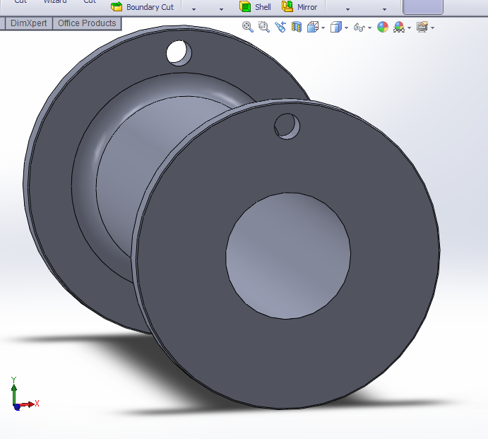
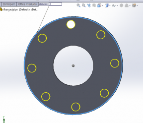
Additionally, patterning can be done in a variety of ways, for example circular. to create a perfect bolt circle, only one hole needs to be defined, then a circle concentric with the intended bolt circle. Define the number of holes, spacing angle (or check even spacing) and its done. This part was made with a revolve tool, I first made half the profile in a sketch plane and spun it around the center axis to create a part.
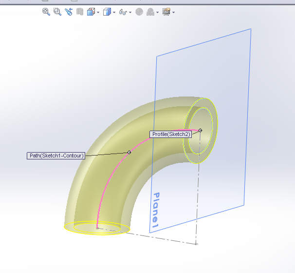
I also practiced my sweep skills, after making a wire coat hanger last week, it was time to go with my pipe theme and try an elbow. This involved making a hollow sweep (two concentric circles form and inner and outer wall) on an arc. To add the flange, I created planes at each end and made extruded features. The bolt hole patterning went the same way as the piece before.
The last and final piece of my pipe experiment had to be a tee. This I started in the same way I made the pipe section with the revolve tool, then I assigned a new sketch (to be revolved) in reference to the middle of the base pipe sketch. After the revolve, I had what looked like a pipe tee, but had all the solid of both pieces. In order to clear it out, I established a reference geometry plane on the end of the joining t section, and made a blind extruded cut down through the blockage. I did this on the end of the base pipe as well, then took a sectional view to make sure it was clear:

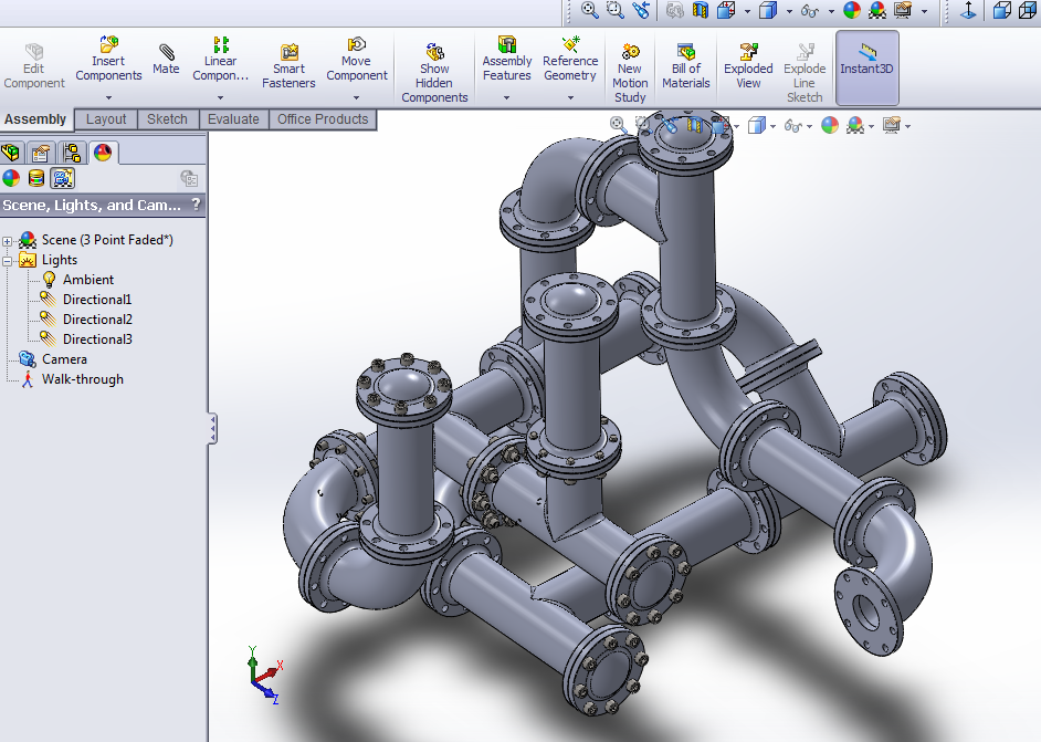
Finally to put it all together, I went into assembly mode and began to pull up and arrange these pieces together. Mating parts, as it is called, involves selecting planes, edges, and corners to be joined. Then relationships are defined; concentric, tangential, coincident, etc. For flanges, their faces were selected and made coincident, the outer edges of the flanges are selected and made concentric. the only degree of uncertainty now is rotational, which can be defined by selecting a bolt hole on each flange and selecting concentric. On some of them I experimented with “Smart Fasteners” which automatically places bolts in the holes in selected groupings of holes. The trouble I encountered seemed to be caused because I had made two aligned sets of hole on a part, to which it assigned a single long bolt. Always more to be learned!